Acorn RISC OS requires a mouse and it is very limited in use without it. This post describes in detail how to create a PS/2 Arduino adapter that connects to the 9-pin Mini DIN mouse port.
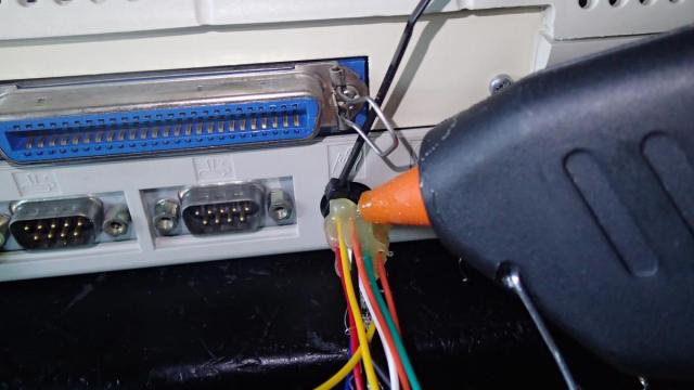
When starting with the project I did not have this rare 9-pin Mini DIN connector, so I was forced to improvise and create a connector out of breadboard wires, a glue gun and a tie strip. First I have inserted the wires into the mouse port, then I have fasten it with a tie strip and finally I used the glue gun to secure it in place. This improvised connector gave me a possibility to build a test circuit. Luckily I have found these 9-pin Mini DIN connectors in a Chinese online shop and ordered a couple of pieces.
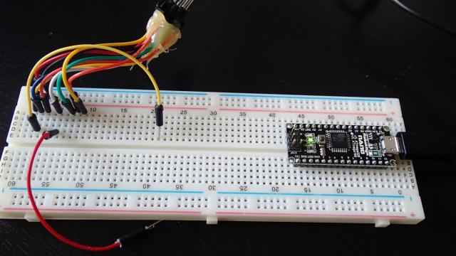
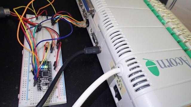
Now I could attach the other end of the wires to the breadboard with an Arduino Nano and start building the circuit.
The idea was to use the Arduino Nano to process the output from a PS/2 mouse and translate it into signals the Acorn mouse port could understand. I was also thinking about creating an USB adapter, but the Arduino Nano cannot function as an USB host, for that you need an Arduino Due or an USB host adapter and I did not have them. To start I needed to understand how the Acorn mouse worked. In the Acorn Risc PC Welcome Guide I have found the pinout of the mouse port.
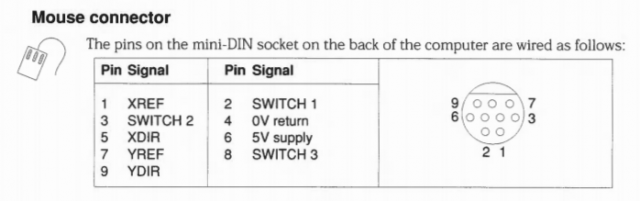
The Acorn mouse is supplied by 5V and the maximum current output of the port is rated at 80 mA, so we can use it to directly power the Arduino Nano. It has 3 buttons and 4 signals that detect the movement of the mouse. To figure out how they work I have consulted the Acorn A3010 Technical Reference Manual. On page 1-15 an explanation is given that each axis of movement is independently encoded in two quadrature signals. They are labeled REFerence and DIRection. For the X axis they are XREF (pin 1) and XDIR (pin 5). This means that when we apply signals to the XREF and XDIR pins in a step-wise manner (like in the diagram below) we will get the mouse cursor moving.
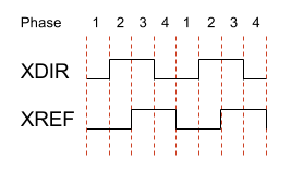
When the signal is translated into binary HI and LOW we can distinguish 4 phases, hence the name quadrature. In this case the mouse cursor will move to the right.
| Phase | XDIR | XREF |
|---|---|---|
| 1 | 0 | 0 |
| 2 | 1 | 0 |
| 3 | 1 | 1 |
| 4 | 0 | 1 |
When we put the XREF signal "in front" the XDIR signal, then the mouse will move to the opposite direction. The same applies to the YDIR and YREF signals.
The next step is to look at the PS/2 part of the design. We will need to find a way to receive the signals that are sent by the PS/2 mouse. A good explanation on how the PS/2 protocol works can be found on the computer engineering website. In short, the PS/2 mouse has 4 pins, 2 of them are +5V power and ground and the other 2 are clock and data signals. The mouse repeatedly sends out 3 bytes of information. The first byte contains the state of the buttons and the next two bytes are the acceleration of the X and Y axis of the mouse. In our case we will be only looking when acceleration is larger of smaller than 1 and then we shall send out our quadrature signal to the Acorn mouse port.
To code the whole PS/2 protocol would be a lot of work, but luckily there is an Arduino library that we can use. It can be downloaded from the Arduino Playground website. Extract the ps2.zip file into the Arduino Library folder and change the include statement in the code, otherwise it will not compile on the new Arduino IDE.
In the file ps2.h on line 11 change:
#include "WProgram.h"
into:
#include "Arduino.h"
Now we can start to create a sketch in the Arduino IDE. We can use the existing PS2 mouse example as our starting point.
The code starts with including of the header file for the PS/2 library.
#include <ps2.h>
The function below will initialise the library. Pin 5 is the mouse DATA pin and pin 6 is the CLOCK pin. Feel free to use whatever pins are convenient.
PS2 mouse(6, 5);
A PS/2 mouse can not only send, but also receive data. In our case we will send some initialisation bytes to the mouse. We are telling it to reset and place itself into remote mode, so we can get the encoder data on demand.
void mouse_init() {
  mouse.write(0xff);  // reset
  mouse.read();  // ack byte
  mouse.read();  // blank */
  mouse.read();  // blank */
  mouse.write(0xf0);  // remote mode
  mouse.read();  // ack
  delayMicroseconds(100);
}
This is the first function that the Arduino IDE is calling. We also initialise the serial port to 9600 baud so we can output the bytes that the PS/2 is sending.
void setup() {
  Serial.begin(9600);
  mouse_init();
}
Get a reading from the mouse and report it back to the host via the serial line. We will change this function later, but at this stage we just want to see what is going on.
void loop() {
  char mstat;
  char mx;
  char my;

  /* get a reading from the mouse */
  mouse.write(0xeb);  // give me data!
  mouse.read();      // ignore ack
  mstat = mouse.read();
  mx = mouse.read();
  my = mouse.read();

  /* send the data back up */
  Serial.print(mstat, BIN);
  Serial.print("\tX=");
  Serial.print(mx, DEC);
  Serial.print("\tY=");
  Serial.print(my, DEC);
  Serial.println();
}
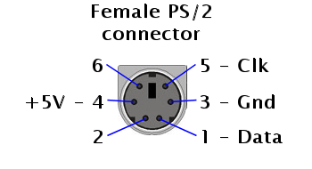
Now it's time to hook up the PS/2 mouse to the Arduino Nano. As we have seen earlier in the code the Arduino is using pins 5 for DATA and pin 6 for the CLOCK signal. The PS/2 port has this pinout:
I did not have a PS/2 female connector at this point in time, but I have found this old DIN-5 to PS/2 converter and I could solder some wires onto it. I have made the following connections from the Arduino to the PS/2 port.
| Arduino | PS/2 port |
|---|---|
| Pin 5 (data) | Pin 1 (Data) |
| Pin 6 (clk) | Pin 5 (Clk) |
| 5V | Pin 4 (+5V) |
| GND | Pin 3 (Gnd) |
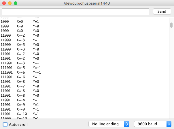
After compiling the Arduino sketch and uploading it we can launch the serial monitor to see what the PS/2 mouse is sending. We can see that the mouse clicks and the movement is being captured.
Now we can proceed to write the code that will catch the PS/2 mouse events and translate the to the Acorn mouse signals. We can use the following code that will trigger them. First we will add some variable declarations for additional Arduino pins that we will be using. Add them just below the #include <ps2.h> statement.
int xrot = 0;
int yrot = 0;

int MBUTTON1 = 2;
int MBUTTON2 = 3;
int MBUTTON3 = 4;
int XDIR = 7;
int XREF = 8;
int YDIR = 9;
int YREF = 10;
Next, add this code on the bottom of the loop() function.
Here we check which mouse button was pressed and set the pin outputs to HIGH or LOW states.
  if (mstat & 0b001) {
    digitalWrite(MBUTTON1, LOW);
  }
  else {
    digitalWrite(MBUTTON1, HIGH);
  }

  if (mstat & 0b010) {
    digitalWrite(MBUTTON2, LOW);
  }
  else {
    digitalWrite(MBUTTON2, HIGH);
  }

  if (mstat & 0b100) {
    digitalWrite(MBUTTON3, LOW);
  }
  else {
    digitalWrite(MBUTTON3, HIGH);
  }
This part of the code sets the quadrature phases that will be sent to the DIR en REF mouse inputs.
The encoding of the phases for the right and up mouse movements:
| Phase | Integer value | Binary value |
|---|---|---|
| 1 | 0 | 00 |
| 2 | 1 | 01 |
| 3 | 3 | 11 |
| 4 | 2 | 10 |
  if (mx > 0) {
    if (xrot == 0) xrot = 1;
    else if (xrot == 1) xrot = 3;
    else if (xrot == 3) xrot = 2;
    else if (xrot == 2) xrot = 0;
  }

  if (my > 0) {
    if (yrot == 0) yrot = 1;
    else if (yrot == 1) yrot = 3;
    else if (yrot == 3) yrot = 2;
    else if (yrot == 2) yrot = 0;
  }
The encoding of the phases for the left and down mouse movements:
| Phase | Integer value | Binary value |
|---|---|---|
| 1 | 2 | 10 |
| 2 | 3 | 11 |
| 3 | 1 | 01 |
| 4 | 0 | 00 |
 if (mx < 0) {
    if (xrot == 2) xrot = 3;
    else if (xrot == 3) xrot = 1;
    else if (xrot == 1) xrot = 0;
    else if (xrot == 0) xrot = 2;
  }

if (my < 0) {
    if (yrot == 2) yrot = 3;
    else if (yrot == 3) yrot = 1;
    else if (yrot == 1) yrot = 0;
    else if (yrot == 0) yrot = 2;
  }
This part of the code translates the most significant byte (MSB) to the REF signal and the least significant byte (LSB) to the DIR signal.
  if (xrot & 0b01) {
    digitalWrite(XDIR, HIGH);
  }
  else {
    digitalWrite(XDIR, LOW);
  }

  if (xrot & 0b10) {
    digitalWrite(XREF, HIGH);
  }
  else {
    digitalWrite(XREF, LOW);
  }

  if (yrot & 0b01) {
    digitalWrite(YDIR, HIGH);
  }
  else {
    digitalWrite(YDIR, LOW);
  }

  if (yrot & 0b10) {
    digitalWrite(YREF, HIGH);
  }
  else {
    digitalWrite(YREF, LOW);
  }
Before connecting the output to the Acorn mouse port I have added some LEDs to check how the code will behave. After some debugging I have managed to trigger the quadrature and mouse signals.
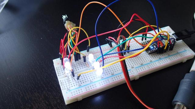
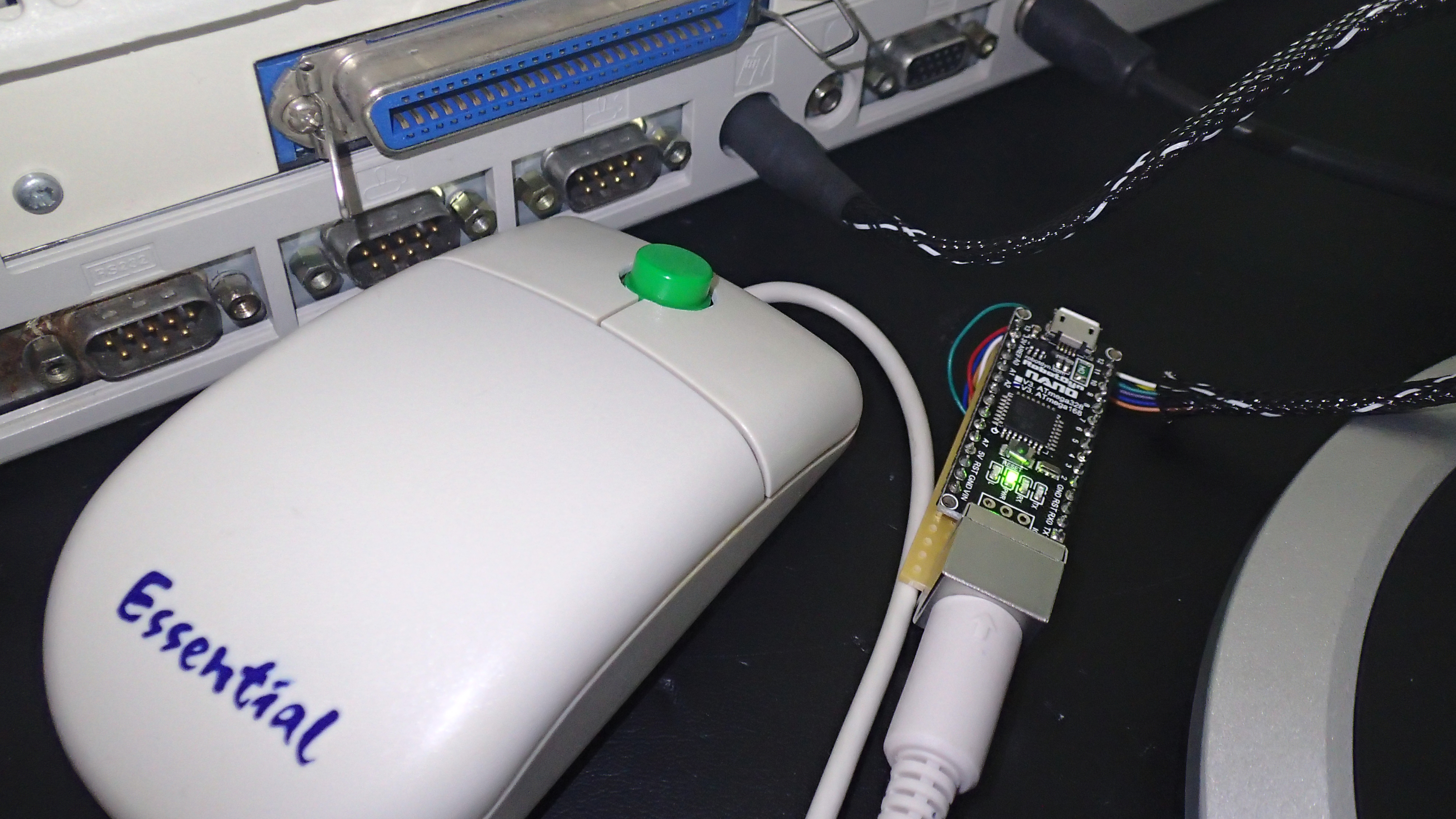
After connecting the breadboard circuit to the Acorn mouse port, I could see that the Acorn RISC OS reacted to the mouse clicks and movements.
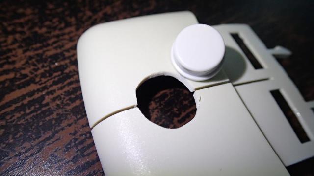
RISC OS is using a mouse with three buttons. The PS/2 mouse that I had, did not have a third button and I was curious if it would be possible to add one. After opening the mouse I could see that it actually had support for an extra mouse button, but it was not build in.
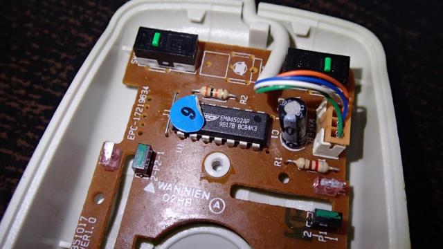
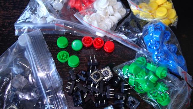
I had some push buttons lying around, so I have decided to add the extra button.
First I have cut an extra opening on top of the mouse that was matching the size of the new button.
Then I could attach the extra button to the casing. I have decided to use the green button as it matched the Acorn design.
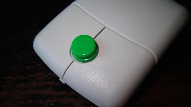
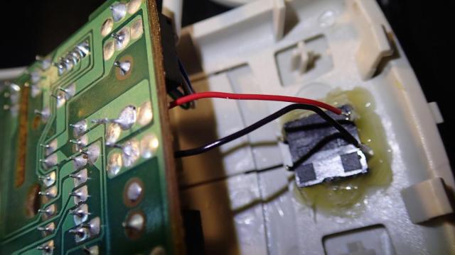
To fasten the button I have used hot glue. Finally I could solder the wires of the button to the PCB.
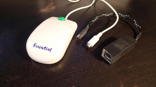
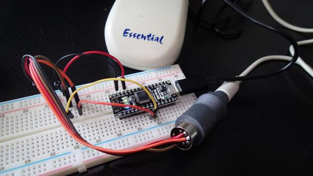
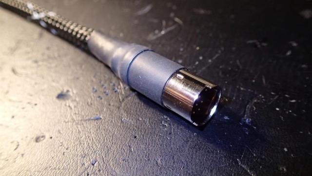
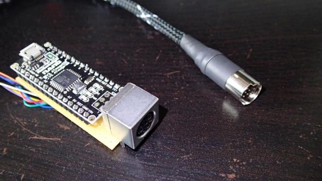
After two weeks the 9-pin Mini DIN and the PS/2 connectors that I have ordered finally arrived and I could start creating the circuit on a small universal PCB. I started with the 9-pin Mini DIN connector. Unfortunately the casing was too large and it did not fit inside the port on the back of the computer, but fortunately I still could use the plug. As the casing I have used heat-shrink tubing. It turned out ok.
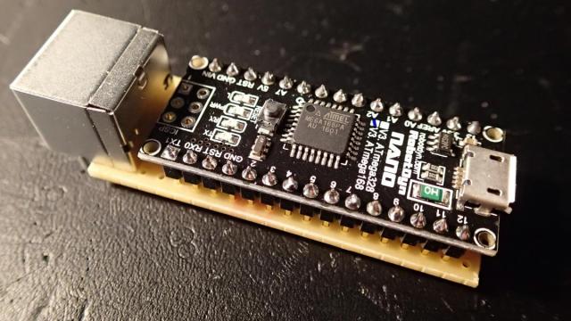
Then I was able to create the small PCB board with the attached female PS/2 connector. It was just big enough so the Arduino Nano could be fitted next to it.
At this point it was a matter of soldering all the connections.
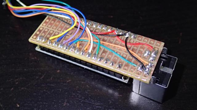
This is the list of the connections from the 9-pin mini DIN connector to the Arduino board:
| 9-pin mini DIN | Arduino |
|---|---|
| Pin 1 | Pin 8 (XREF) |
| Pin 2 | Pin 2 (Switch 1) |
| Pin 3 | Pin 3 (Switch 2) |
| Pin 4 | GND |
| Pin 5 | Pin 7 (XDIR) |
| Pin 6 | 5V |
| Pin 7 | Pin 10 (YREF) |
| Pin 8 | Pin 4 (Switch 3) |
| Pin 9 | Pin 9 (YDIR) |
Below are the connections from the PS/2 connector to the Arduino board:
| PS/2 female connector | Arduino |
|---|---|
| CLK | Pin 6 |
| DATA | Pin 5 |
| 5V | 5V |
| GND | GND |
The finished board looked like this:
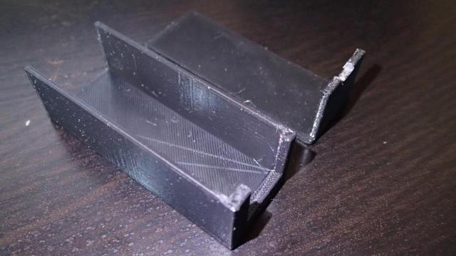
To finish the project I have decided to design a case for it that could be printed with a 3D printer. This is the design for the Arduino Nano PS/2 casing that I have come up with.
This has turned out to be a large blog post. I have enjoyed every step of the creation of this mouse adapter. In the end I was glad that Eric could not find the Acorn mouse, otherwise I would not be able to do this project.