
After hooking up of all the connections to the RAMPS 1.4 board we will need to provide power to the board. The standard 5V output of the USB connector is only sufficient to power the Arduino and the LCD display, so we will need external power. The minimum power that needs to be provided is 12V x 20A (240W). But just to be sure we will use a 12V x 30A (360W) power supply.
Searching on eBay with the keywords "12v 30a power supply" will show you a lot of options where you can get it. They are usually manufactured in China. I have bought mine in a Chinese online shop, they cost around 25 euros.

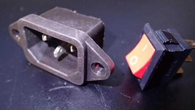
Hooking up the power supply is easy, keep in mind to use thicker wires for the 12V output. Mine were 0.82 mm² (18AWG). You will also need a power cord, standard 3 pin computer cord (C13 IEC) will do. To make it nice and neat you can also use Red Button Rocker Switch with 3 Pin IEC320 C14 Power Socket Connector.
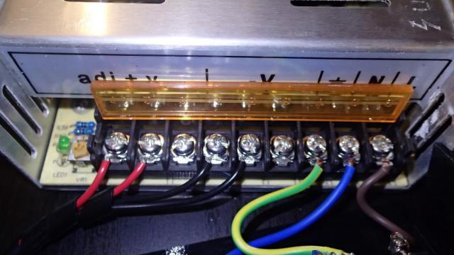
First you will need to connect the high voltage wires: Ground, (N)eutral and (L)ine on the right of the power supply. In Europe they have the color encoding that you see on the picture. Also connect the 12V output wires. This power supply can connect up to 3 pairs, we are only using 2.
Attach the switch and the C14 connector to a printed power supply cover. I can not find the design that I have used, but when you search thingiverse with the keywords: cover power supply, you shall find many nice solutions. Now you can solder the wires of the switch and the C14 connector like on the picture below.
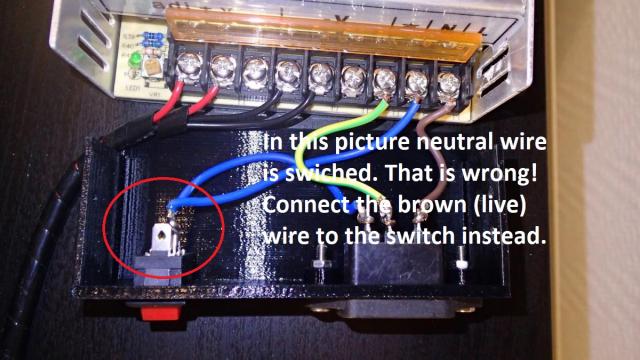
One of the readers of this blog (Suusi) has noticed an error in the connection. I have switched the Neutral, but this is extremely dangerous. In the event of a fault developing between the Earth and the Neutral the power cannot be isolated or switched off. The Neutral is at earth so that the switch and or fuse must always be in the Live to isolate the supply in the event of a fault. (Thanx Suusi)
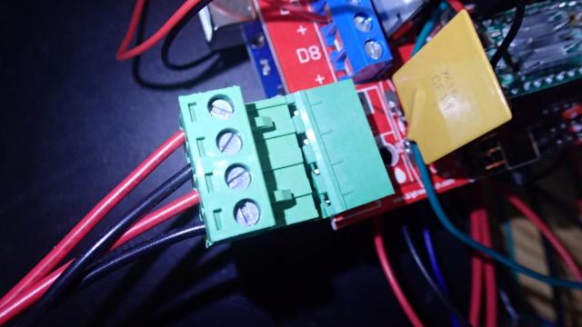
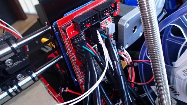
On the RAMPS 1.4 board there is a green connector when you can attach the 12V wires from the power supply with screws.
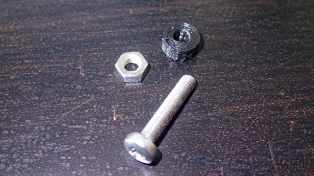
After you connect it we can mount the whole board on the aluminum frame of the Prusa i3 printer. We will need to print 3 times the ARDUINO-WASHER.stl model that is inside the Prusa i3 Rework set and three M3 x 16 mm screws with nuts.
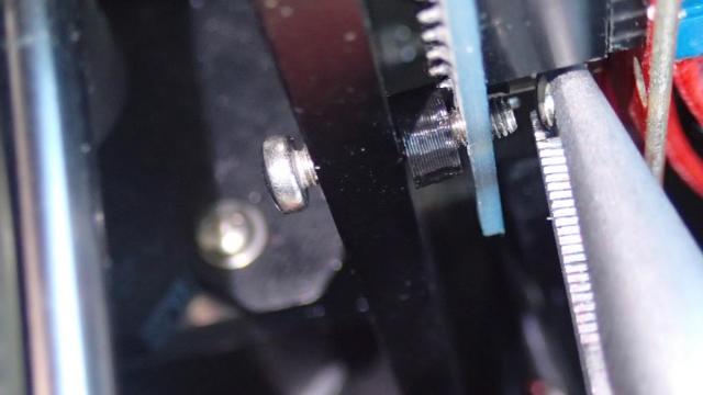
Now place the RAMPS board on the left back side of the aluminum frame.
And screw it with tight. The washer needs to be between the frame and the board to prevent shortcuts.
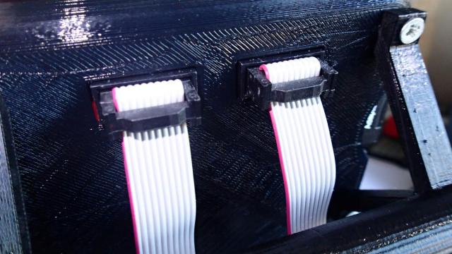
The last thing is to connect the LCD display to the RAMPS board. Use the provided cables and connect them to the board.
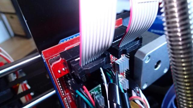
And to the display module that we have mounted before. The left connector on the RAMPS is attached to the left side of the LCD screen.
We have reached the point where we are going to talk about Marlin firmware and the configuration for this specific 3D printer setup.