In the first part we have investigated and assembled all the parts to build the frame. Now it is assembled to assemble the base of our 3D printer.
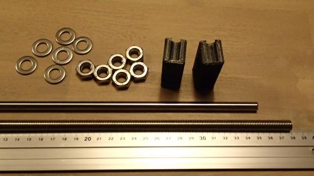
To begin we will first need 2x M10 x 380 mm threaded, 2x 8 mm x 350 mm smooth rods, 4x Y-Corner pieces, 12x M10 nuts and 12x M10 washers.
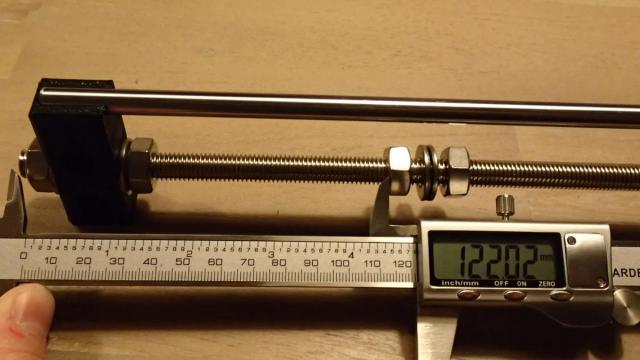
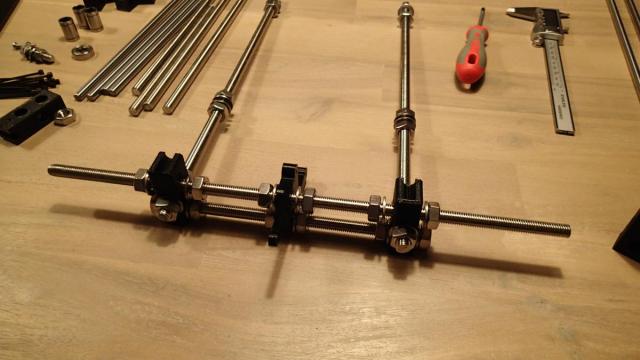
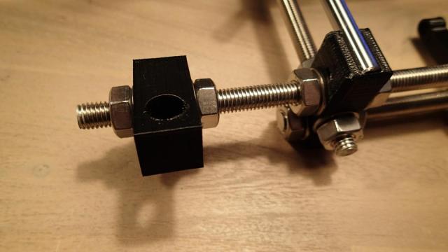
Start building the rail and make sure there is 122 mm between the beginning of the rod and the nut in the middle. The 6 mm aluminum frame will be placed between these 2 nuts.
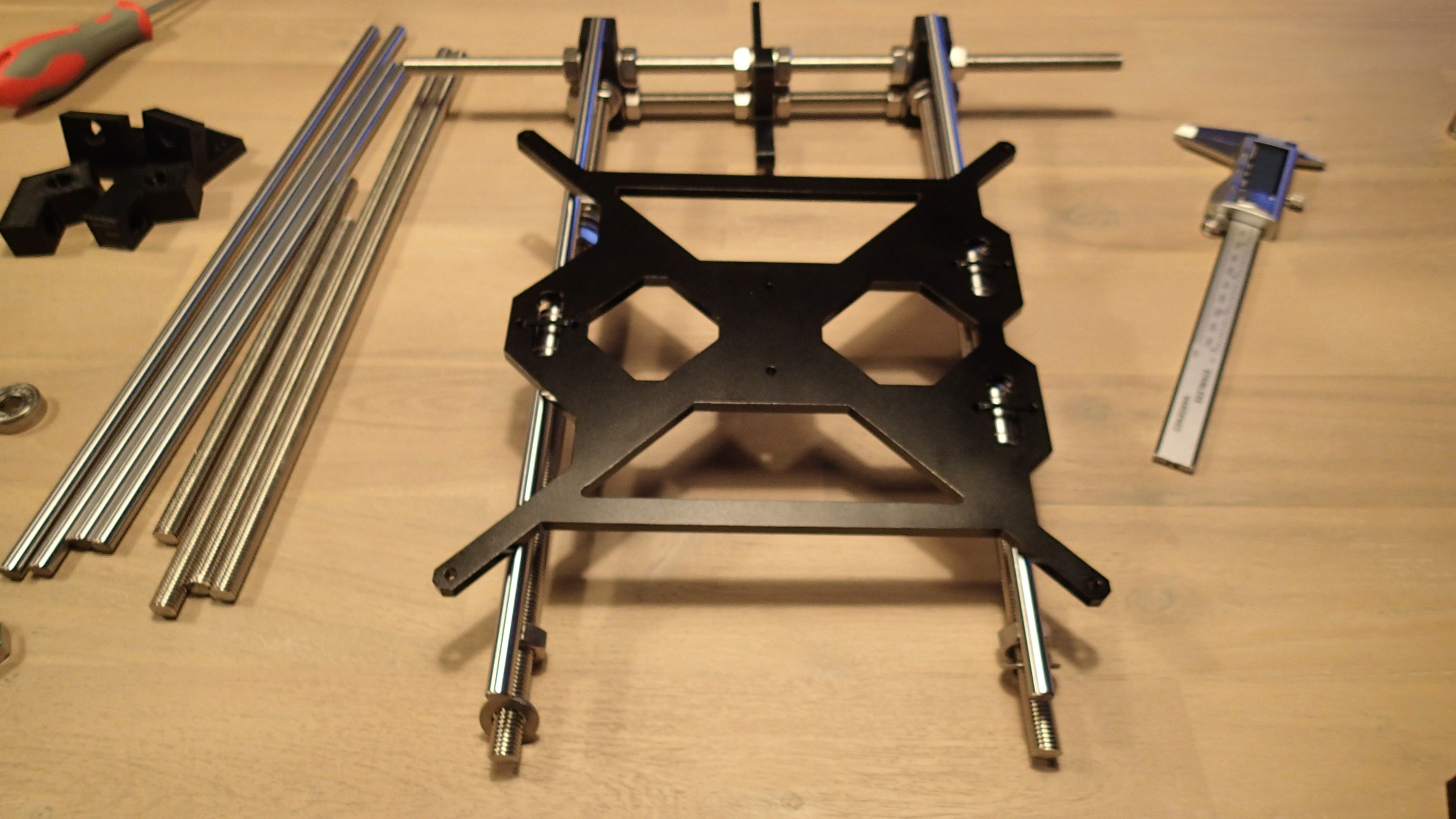
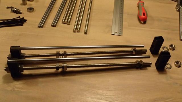
Now build the 2 rails just like shown in the picture below. Do not tighten the end of the Y-CORNERS just yet.
Build the back of the frame using M10 x 210 mm, M10 x 370 mm threaded rod and the Y-MOTOR part. The distance between the 2 smooth rods needs to be 170 mm. The stepper motor will be mounted on the right and the shaft with the pulley will be on the left, so the gap on the left (between the Y-CORNER and Y-MOTOR parts) needs to be around 75 mm and the right around 65 mm.
It's time to put the linear bearings on the sliding bed platform.
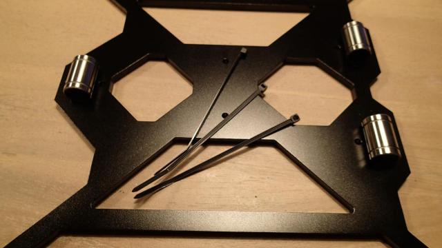
You can tighten them with the cable ties like this.
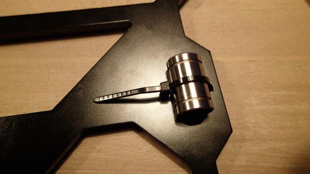
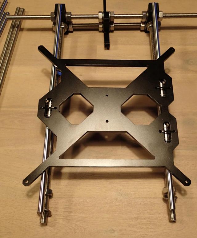
And then slide them on the rods.
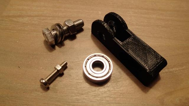
Assemble the Y-IDLER. For this you will need the 608 bearing, 1x M8 x 30mm bolt with nut and washers, 1x M4 x 20mm bolt with nut and the 3D printed part.
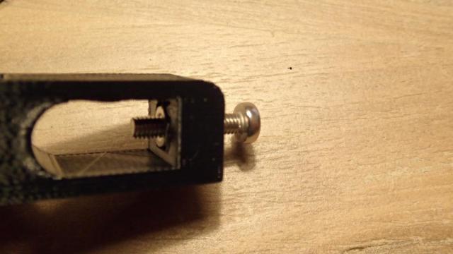
Now place the M4 nut inside the Y-IDLER just like this and screw in the nut.
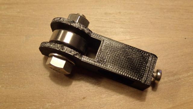
Assemble the 608 bearing with the M8 bolt just like shown in the picture.
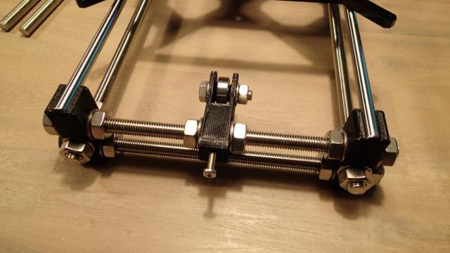
Finish up the front of the base structure of the 3D printer frame and place the Y-IDLER in the middle. The M4 bolt will be used to adjust the tension of the belt.
Now add the support brackets on both sides of the M10 x 370 mm threaded rod on the back of the frame. They will help to support the 6 mm aluminum frame.
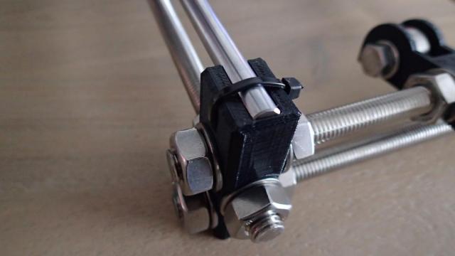
Tighten the 8 mm steel rods to the Y-CORNERS with cable ties.
In part 3 we will add the stepper motor and the belt that will move the printing bed in the Y direction.