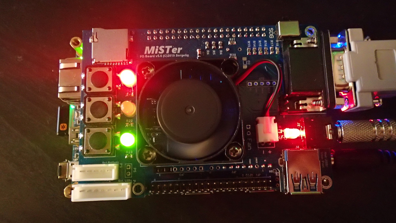
MiSTer project that is installed on the DE10-Nano board can only output video using the on-board HDMI connector. However if you want to get the real retro gaming experience then you can attach the MiSTer IO Board. Among other things, this add-on board let's you output 15KHz analog RGB video and audio signals that will let you connect to a CRT monitor. This blog post describes how to build such a board.
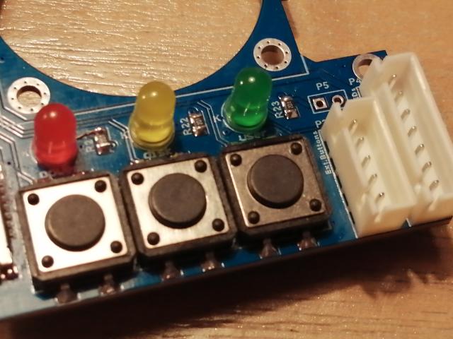
The MiSTer IO board also gives you other advantages. There are three buttons that will let you access various functions of the MiSTer like reset, call of the on-screen-display (OSD) and an user defined option. The three LEDs indicate power, disk access and the green LED shows user defined functions that differs per core.
Other options on the IO add-on board are:
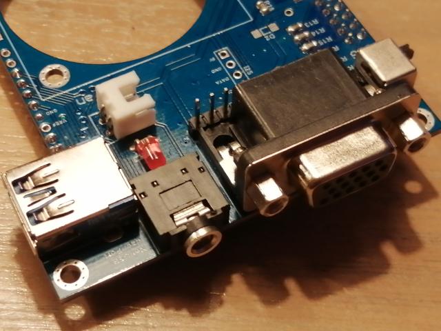
- SoG switch, that can output a sync-on-green signal on the DB15 connector
- Output port that looks like USB 3.0, but it is an expansion connector
- Secondary SD card slot, that is used by some cores
- FAN for cooling the FPGA
- Additional connectors to integrate the MiSTer into cases
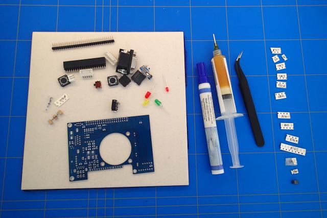
In the previous blog I have described the process of how to get the MiSTer IO board PCBs manufactured. Now it is time to solder the required components.
To start we need to gather all the parts that we need to solder. On the github wiki page you can find the bill of materials. The only parts that are missing on that list (for board 5.6) are R39 up to R44. These are 0805 10K 5% resistors.
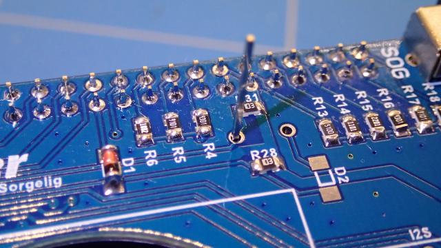
We start to solder the back side of the board with the 0805 capacitors and resistors.
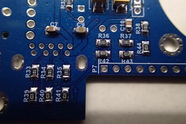
Then we can solder the tantalum capacitors. Notice that they have polarity and have to be soldered correctly. On the board there is a dot where the plus pole need to be soldered. On the tantalum capacitor the line indicates the positive polarity.

Now you can flip the board to the front side and solder the remaining resistors, D1 diode, SD slot and the tactile push buttons.
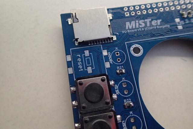
Solder the 5mm LEDs and the XH2.54 connectors.
Some tips on the polarity of the LEDs:
- The longer lead on the LED is "MORE", so it is positive.
- Looking at the LED (through the plastic cover) the metal of the ground plane is larger. And we all know that ground is marked as negative.
- When the leads are cut off, you can see by the cut on the LED where the negative side (cathode) is located.
- In the schematics of the LED the minus is where the inverted K is located (for cathode). It is also marked with a K on the MiSTer board.
- If you are not sure, you can always measure it. In the schematics, the cathodes of the LEDs are connected together and by investigating the PCB, you can see that too.
- Current flows from the anode (+) to the cathode (-) and never in the opposite direction, so when you solder it wrong the LED will not light up.
Continue to solder the rest of the connectors like SoC switch, VGA, audio jack, USB 3.0 port, the fan connector and the 3mm power led.
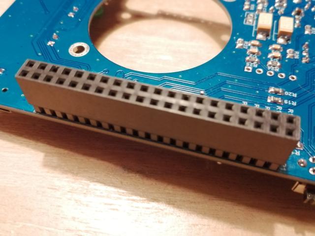
Next solder the double row 40-pin female header.
Finally solder the long male header pins. First connect the IO board to your DE10-Nano board and insert 8 of the pins to the board like on the picture. Remove one of the pins next to the VREF label (you will need it later).
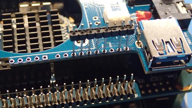
Now solder and cut off the part of the pins that is sticking out.
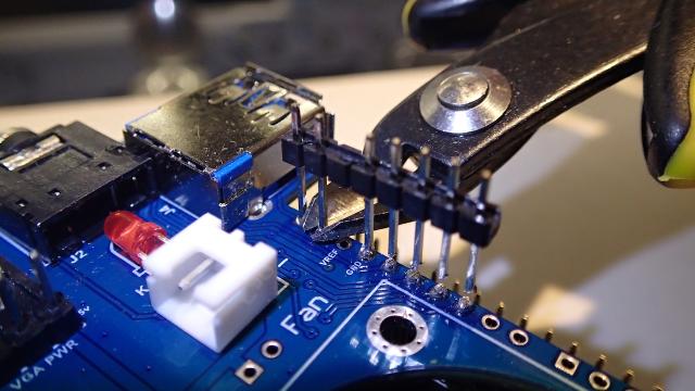
Now use the pin you just removed and insert it into P9. Solder and cut off as you did with the other pins.
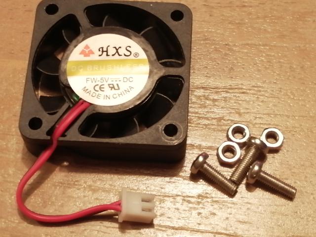
You should now have a working MiSTer IO board. Optionally you can solder I2S and VGA Power pin headers. For better cooling you can install a 40x40x10 mm fan with a XH2.54 2-pin connector. To attach it you can use three 10 or 12 millimeter M3 screws with nuts.
Contact me if you need help with the assembly. You can also buy this fully assembled board in the ezContents store on Tindie.