In this blog series, I will cover the build of my Prusa MK3S 3D printer clone. My goal is to reduce the costs of the original while keeping the quality as high as possible.
A couple of years back I built a clone of Prusa MK2. If you are interested you can read about it here.
This is a completely new series. First I will describe the build of the base of the printer. It consists of the frame and y-axis assembly.
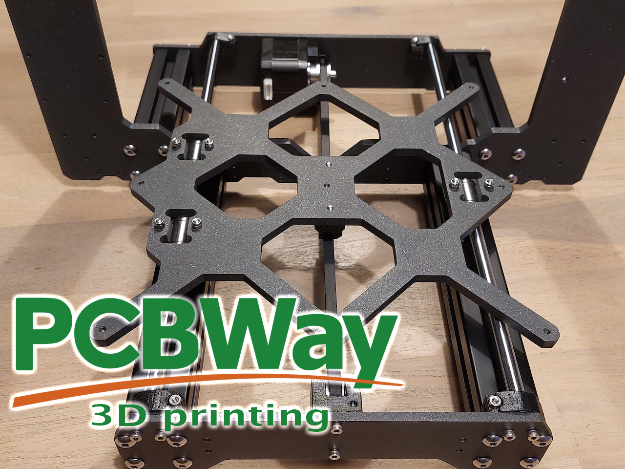
PCBWay kindly offered to sponsor this 3D printer build. Next to PCB manufacturing and assembly services they also offer 3D printing services in various printing technologies like FDM, SLA, SLS, MJF, DMLS and Polyjet.
It is not unimportant to mention that the whole Prusa MK3S assembly is open source and it makes this clone build possible. The specifications of all of the parts can be found online. If you want to take it to the extreme it is even possible to manufacture (almost) all of the parts yourself. Prusa MK3S frame design (DXF) files, the length of the 3030 aluminium profiles and all the latest versions of the printed parts can be found inside this GitHub repository.
The diameter of the smooth rods for the Y-axis is 8mm and the length is 330mm.
There are Prusa frames out there that are completely made out of aluminium profiles, but I do not like them. In my opinion, they don't look that nice and I think that structural integrity is better when the frame is cut out of one piece of thick sheet. The thickness of the frame is around 6.2mm.
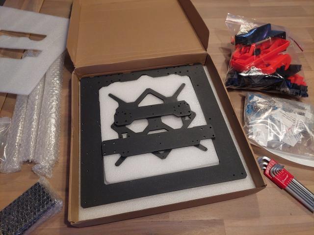
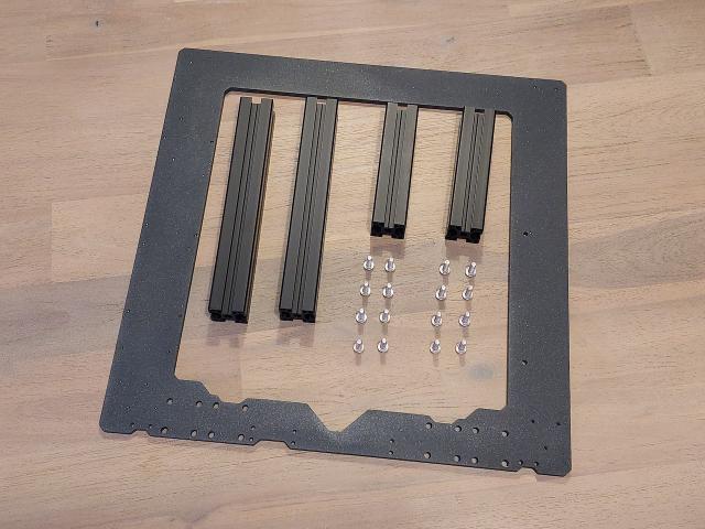
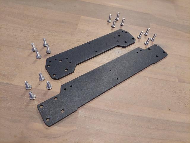
The Prusa clone frame that I received was rather neatly packaged, there was no damage to the parts. It consisted of the aluminium frame cutout, aluminium profiles, and also front and backplates. The 8mm aluminium rods were also included in the set.
All the plastic parts that are needed to build the Prusa MK3S+ printer can be downloaded from this location. It is a good idea to use PETG to print all of the parts.
The only missing parts to complete the frame were the M5x16 button screws, which I had to order separately.
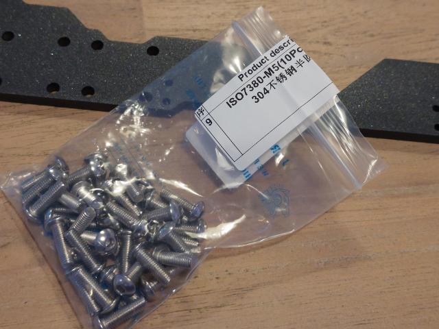
We will need 32 of them to complete the frame.
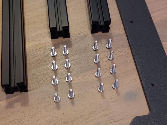
Start the build by collecting these parts. Set aside the first 16 screws.
The longer profiles go in front of the frame.
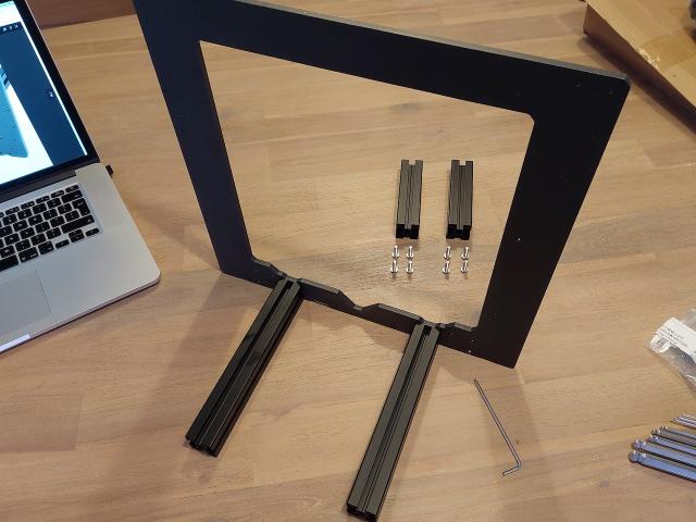
Do not fasten the screws tightly yet as we will need to align the whole frame first.
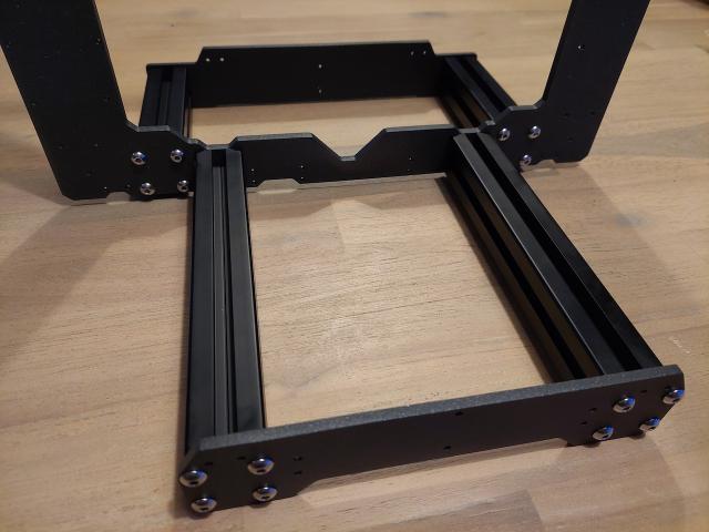
The next step is to lightly fasten the shorter profiles to the other side of the frame.
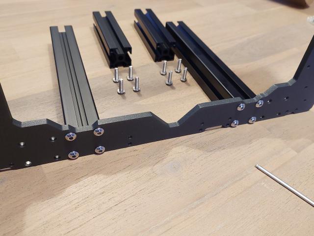
Gather the rest of the screws together with the front and backplate.
Attach the front and the backplate as shown in the picture.
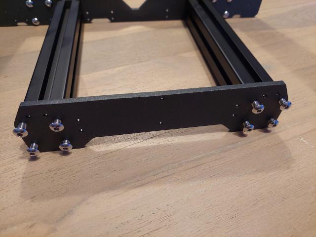
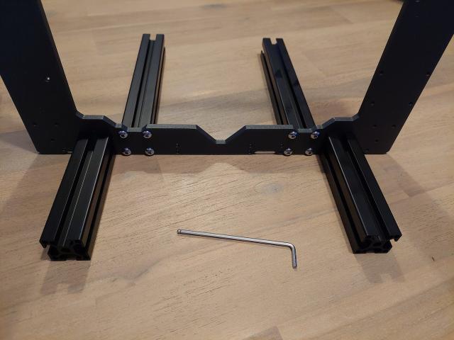
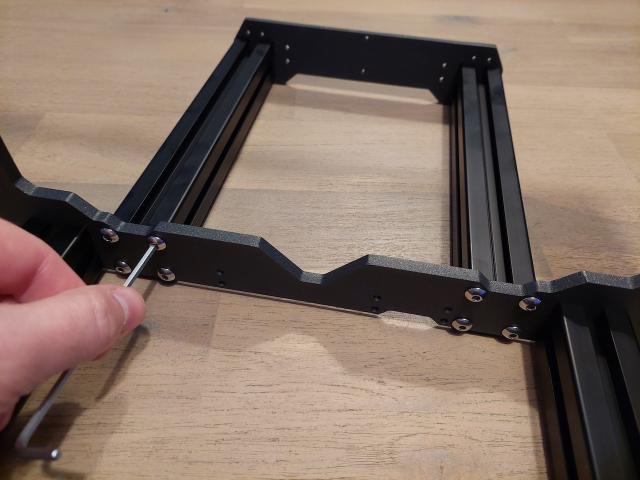
The frame is now complete. Make sure you place the frame on a flat surface and start to fasten the screws.
First, the profiles that connect to the frame. Fasten the screws diagonally. Then the front and backplate. You might need to untighten and tighten the screws if the frame is still wobbly. It took me some time to complete the frame.
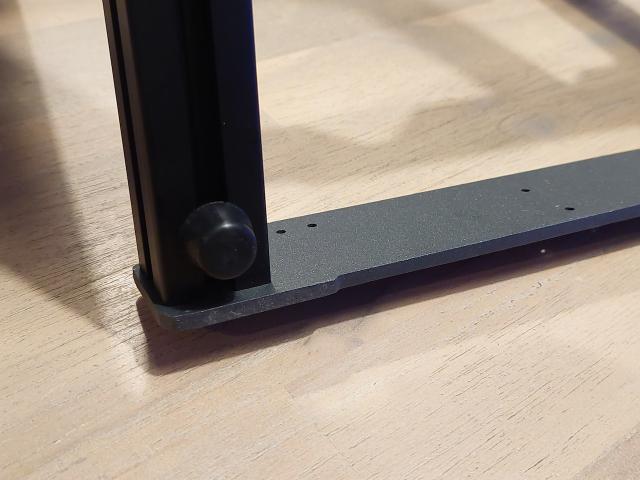
However, these rubber feet will help to even out the frame if it is still a bit uneven. Prusa mentions that it is against the vibration, but I think that it is also to stop the frame from wobbling. Prusa MK2 frame did not have this issue as the base was constructed from aluminium threaded ends connected with self-printed parts and it was easier to alight them.
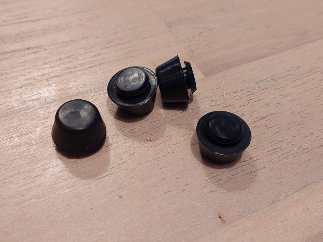
The feet can be easily attached.
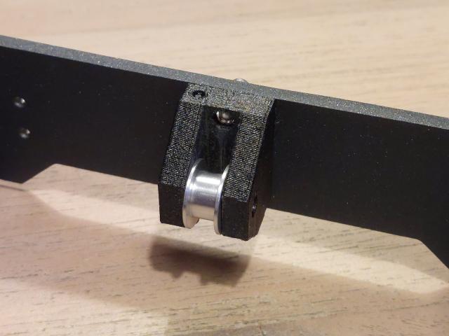
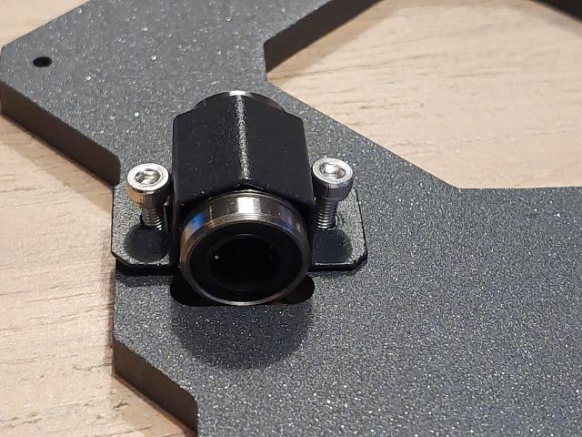
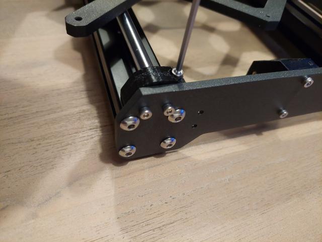
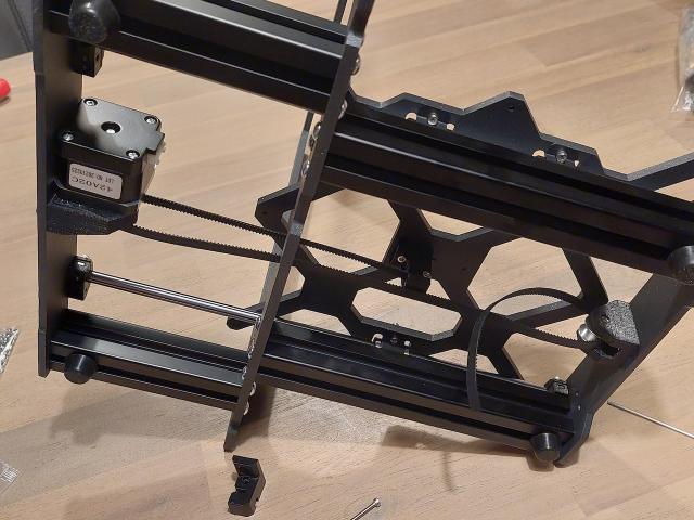
The next part to install is the Y-belt-idler. You will need:
- M3x10 screw (2x)
- M3 Hex nut (2x)
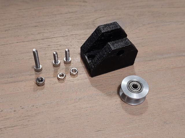
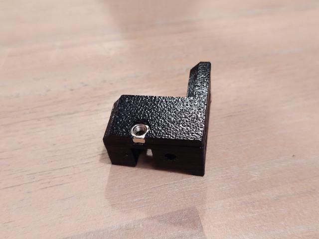
First insert both hex nuts into the holes that will attach the part to the frame front plate.
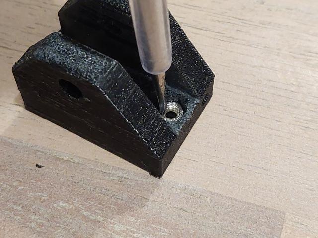
The nylock nut goes into the hole on the side of the part.
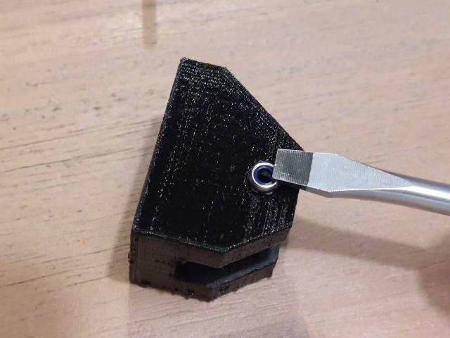
I cleared the inside of the idler with a small file as the print came out with some Z-wobble on my old 3D printer. Let's hope things will improve after this build is finished.
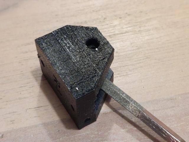
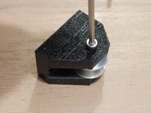
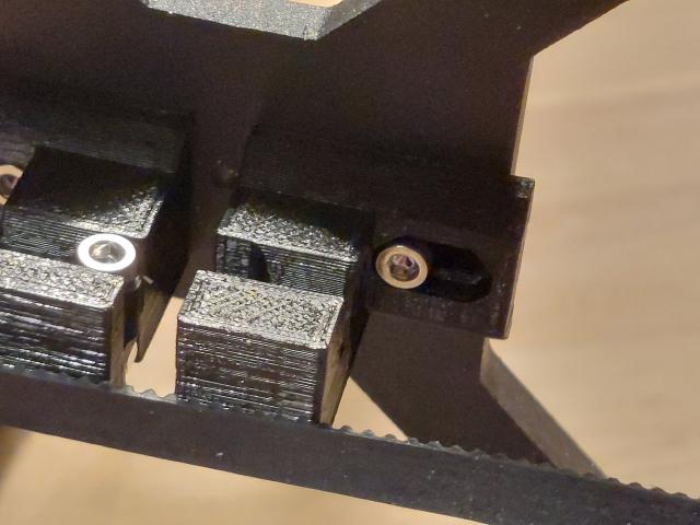
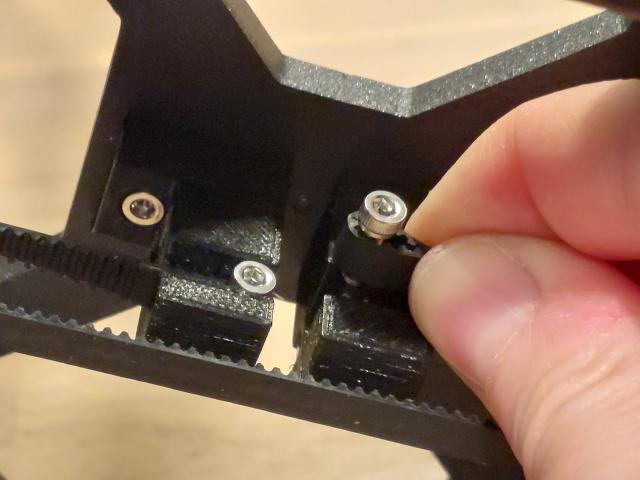
Insert the M3x18 screw together with the roller bearing pulley.
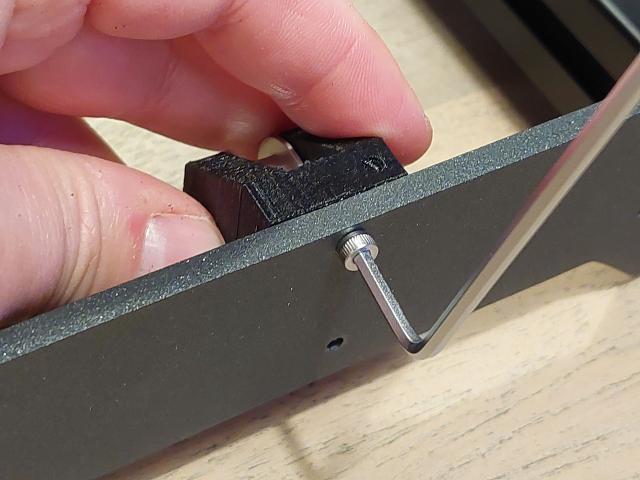
Attach the idler to the front plate using the two M3x10 screws.
After the installation, it should look like this.
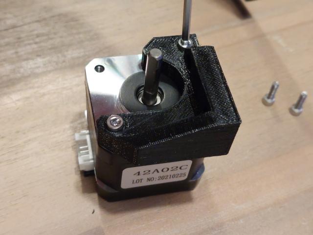
Prepare the following parts to install the y-motor:
- NEMA 17 stepper motor which is labelled with the Y-tag.
I have bought this Prusa clone stepper motor set. The dimensions and specifications are similar to the original ones.
Initially, I bought this set of motors, but the connectors that are sticking out make it a bit harder to mount them exactly as recommended by Prusa. The Z-axis also requires a lead screw that needs to be connected using a coupler.
- M3x10 screw (4x)
- M3 Hex nut (2x)
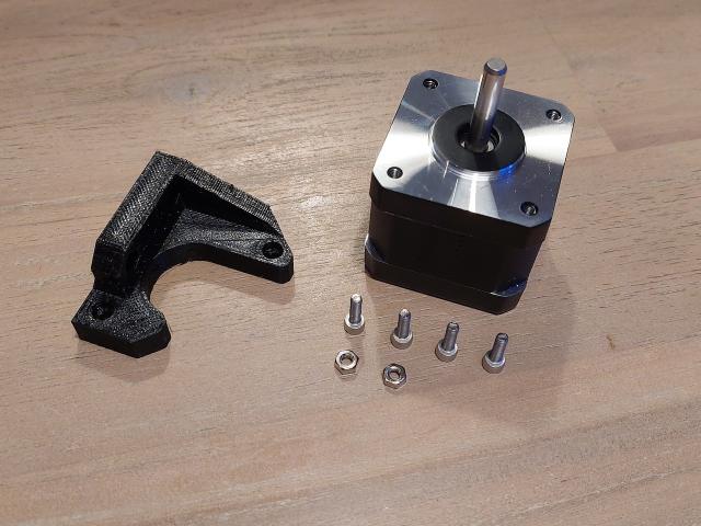
Place the M3 hex nuts inside the holes of the Y-motor-holder part.
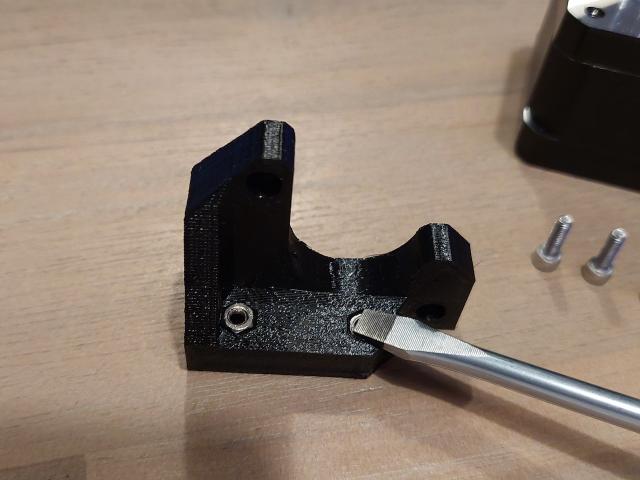
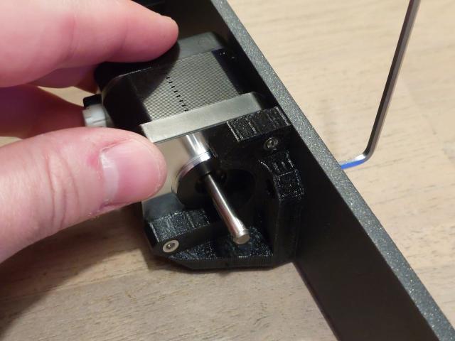
In the picture below, I am using the older stepper motor (with the plastic connector), but later I will replace it with one where the cable is already attached.
Connect the part to the stepper motor using the M3x10 screws.
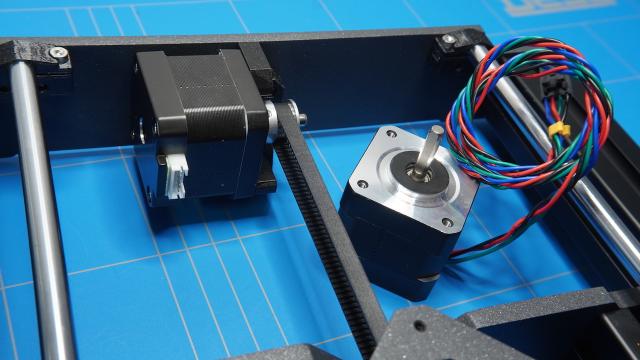
And attach it to the backplate using the two remaining M3x10 screws.
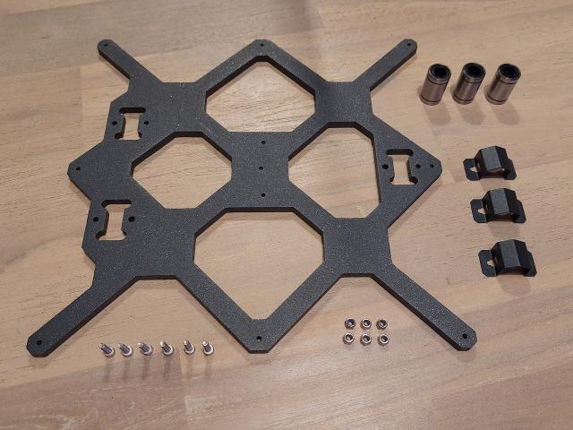
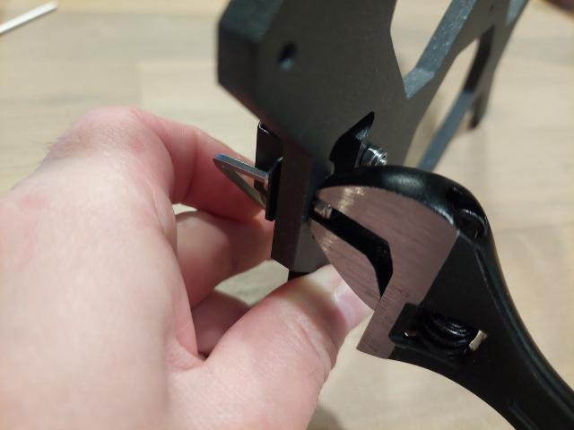
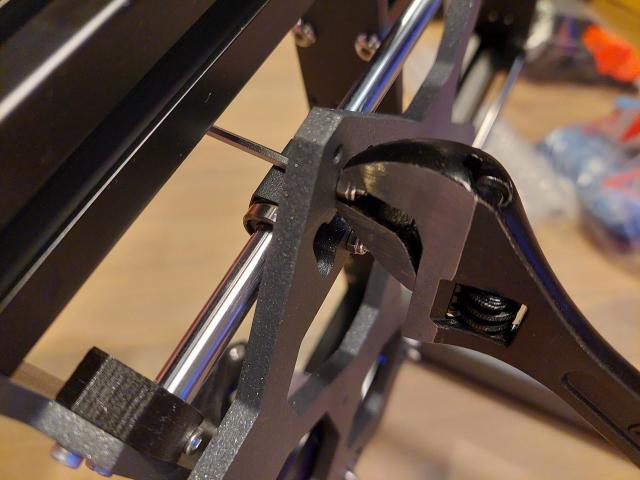
Prepare the y-carriage parts. You will need:
- LM8UU Linear bearing (3x)
- Bearing clip (3x)
- M3 nylock nut (6x)
- M3x12 screw (6x)
Place the linear bearings on the y-carriage oriented like this.
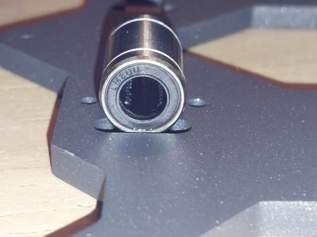
And fasten them using two M3x12 screws.
I grabbed the nylock nut on the opposite side using an adjustable wrench and tightened the screw with a hex key. Do not tighten the nuts all the way yet.
Locate the middle size 8mm smooth rods
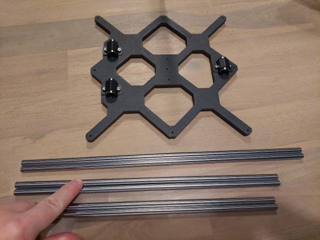
And insert them onto the linear bearings.
Prepare the following parts to fasten the smooth rods to the frame:
- Y-rod-holder part (4x)
- M3x10 screw (12x)
- M3 square nut (12x)
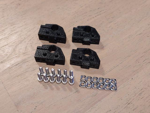
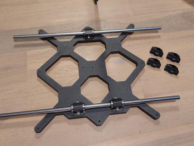
Insert a total of 8 square nuts on top of the y-rod-holder parts.
And the remaining 4 on the side.
End result should look like this.
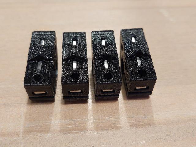
Now slide the smooth rod on the y-rod-holders.

And fasten the rods to the frame using the M3x10 screws (12x).
Check if the Y-carriage is sliding smoothly and then firmly fasten the nylock nuts.
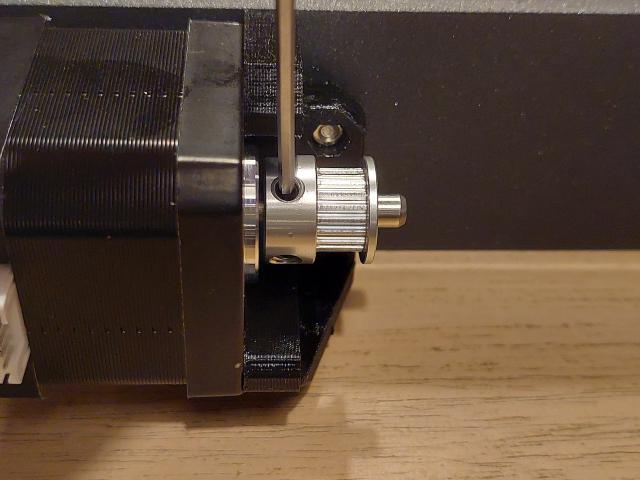
Insert the pulley onto the Y-motor and fasten it just like in the picture. Initially, I used a pulley with 20 teeth but later found out that the original Prusa is using one with 16 teeth. Although it is possible to configure it using the 20 teeth version, I have chosen to replace it later with the 16 teeth version. In a future blog post, I will describe the whole process. The complete spec of this pulley is:
- GT2 Timing Belt Pulley 16 teeth, 5mm Bore and 6 mm belt width
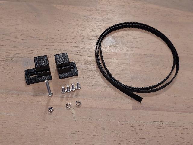
For the next step you will need the following items:
- Y-belt-holder and Y-belt-tensioner 3D printed parts
- GT2-6mm timing belt with a length of 650 mm
- M3x10 screw (4x)
- M3x30 screw (1x)
- M3 Hex nut (2x)
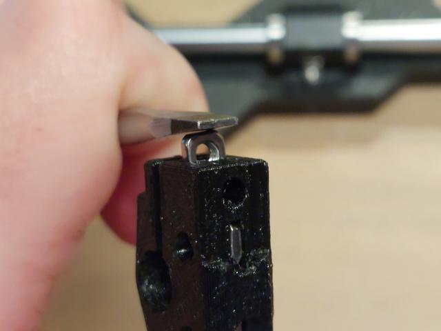
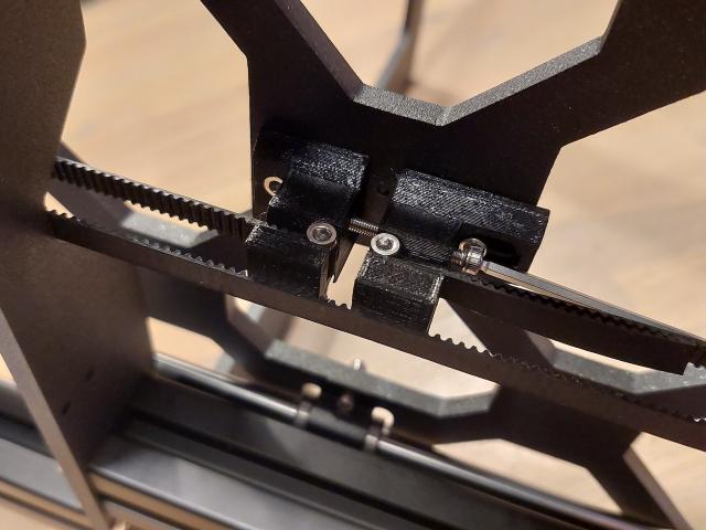
First, insert the M3 nylock and hex nut into the Y-belt-holder part
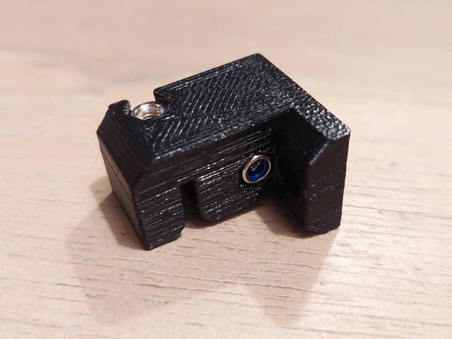
Then wrap the GT2 timing belt around the M3x10mm screw like in the picture
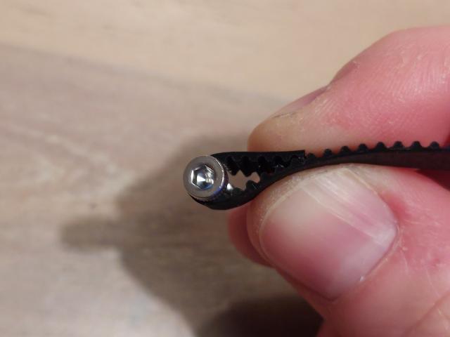
and squeeze it inside the Y-belt-holder like in the picture. The screw should be able to grab the M3 hex nut that is underneath. Fasten it, but not too much, so you won't deform the belt.
Now attach the part under the Y-carriage using an M3x10 screw.
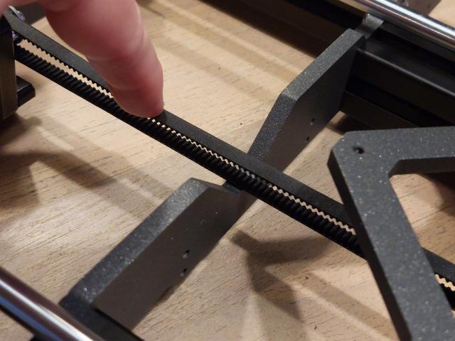
Lead the GT2 timing belt through the pulley on the stepper motor and the roller bearing pulley like in the picture.
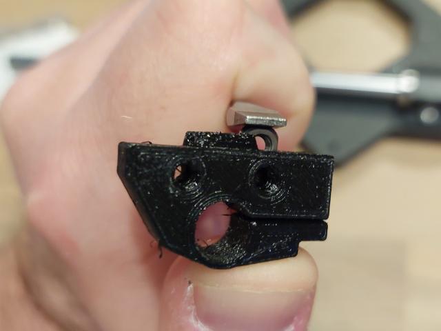
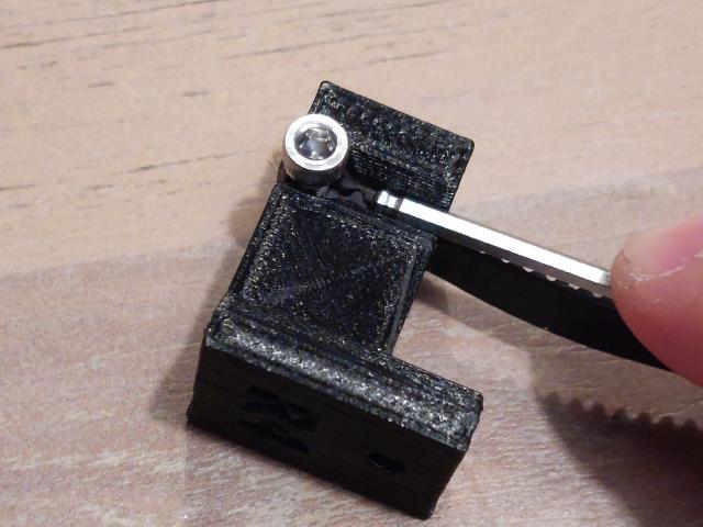
Make sure you have the Y-belt-tensioner part prepared by inserting the M3 hex nut.
And attach it next to the Y-belt-holder using an M3x10 screw, but do not tighten the screw completely just yet.
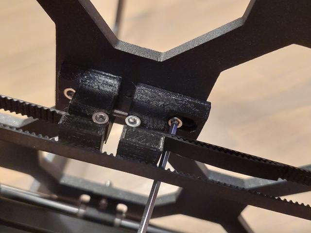
Then stretch the GT2 timing belt that is wrapped around the M3x10 screw and insert it into the Y-belt-tensioner part as shown in the picture. Just like previously it should grab the M3 hex nut on the opposite side.
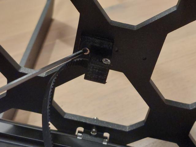
Now you can stretch the GT2 timing belt using the M3x30mm screw by inserting it into the Y-belt-tensioner. The nylock nut will hold the screw firmly in place.
Do not overstretch the belt. You should still be able to push it down with your finger, but don't worry. Later we will adjust the tension precisely using a built-in belt test inside the Prusa firmware.
Do not forget to tighten the M3x10 screw that is holding the Y-belt-tensioner part.
At this point, we are done with the build of the Y-axis. The Y-carriage should be able to slide smoothly without using too much force. In the next part, we will build the X and Z-axes of our MK3S Prusa 3D printer clone.